The label inside the panel indicates that branch circuits cannot be larger than 70 amps. Instead I am hoping to add a sub-panel to serve an upcoming kitchen renovation.
 Tt 0218 Circuit Breaker Panel Flickr Photo Sharing Wiring Diagram
Breaker Panel Wiring Diagram Wiring Diagram Breaker Box Wiring Diagram.

Diagram of pushmatic circuit breaker panel wiring. The white wire is used for hot in this circuit and it is marked with black tape on both ends to identify it as such. These directions will be easy to understand and apply. The previous homeowner had a 220 power source removed from the 2 poll 30amp Pushmatic circuit in the breaker box due to the reason for the power was no longer in use pool pump.
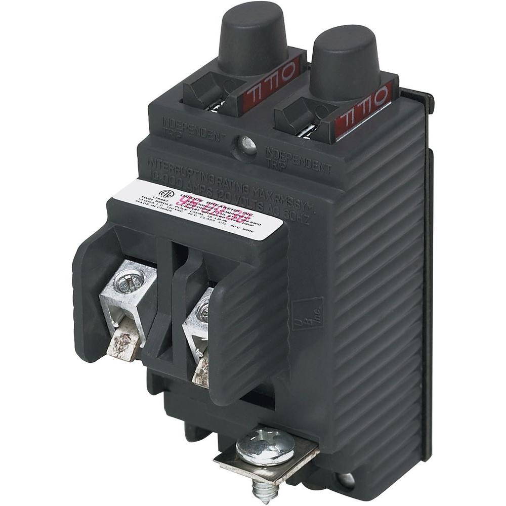
A breaker panel box 15amp 20amp 30amp 50amp and gfci breakers. Instead the breakers are rectangular buttons you must push to activate or deactivate. Is that the main breaker.
325 amp panel wiring diagram guitar a breaker box bo schematics rj45 to db9 residential 200 main eaton how circuit works electric wired fuse center for service 99 100 homeline install 50 2 pole ge diagrams do it square d siemens volume 1 tab my calculate your home s electrical 1972 85 ski doo load on plug qo 42 e 52 pushmatic installation outdoor 1997 inside rating of add. Its meant to assist each of the typical user in building a suitable program. Now Im trying to learn about the old Pushmatic breakers and about home electrical wiring in general.
2 Pole Circuit Breaker Wiring Diagram Every electrical structure is composed of various different pieces. This page contains wiring diagrams for a service panel breaker box and circuit breakers including. I purchased a home built in Lansing Michigan in 1962 with a Pushmatic Breaker Panel.
I have a 1965 Pushmatic main panel with 200 amp service. About Press Copyright Contact us Creators Advertise Developers Terms Privacy Policy Safety How YouTube works Test new features Press Copyright Contact us Creators. In the sub-panel box the neutral and ground wires will connect the same as they do in the main breaker box but the red and black wires will connect to the hot bar instead of.
15amp 20amp 30amp and 50amp as well as a GFCI breaker and an isolated ground circuit. There does not appear to be a main shutoff. 8-gauge wire goes with 40- or 60-amp two-pole breakers.
If not the structure will not function as it ought to be. The existing breakers have been working fine so Im not in a rush to swap it out. The neutral wire is designed to carry an unbalanced load between the two phases of the circuit.
Circuit Breaker Panel Box Wiring Diagram. The wiring into a breaker must correspond to its amperage. This circuit breaker wiring diagram illustrates installing a 20 amp circuit breaker for a 240 volt circuit.
These panels used circuit breakers made by Bulld. Is the least efficient diagram among the electrical wiring diagram. The Pushmatic panel board was a widely used circuit breaker panel installed in homes built between 1950 and 1980.
Wiring Diagram arrives with several easy to stick to Wiring Diagram Guidelines. Also there are no conductors to that breaker. Phantom trips on 100A main Bulldog Pushmatic circuit breaker.
Seems like that is the wrong spot if it is. A 3-wire circuit is not suitable for a electric clothes dryer. Inside the covering youll find a copper wire the ground wire a white covered wire the neutral wire a black wire the hot wire and a red wire another hot wire.
It has worked fine up to about 2 years ago. This diagram illustrates some of the most common circuits found in a typical 200 amp circuit breaker service panel box. The 122 gauge cable for this circuit includes 2 conductors and 1 ground.
Its components are shown by the pictorial to be easily identifiable. Aug 8 2016 - Clear easy-to-read wiring diagrams and instructions for household circuit breakers including. I was thinking that it didn.
I read your page on bulldog pushmatic breakers. The meter is a 100200 amp. Home Circuit Breaker Panel Wiring Diagram It is far more helpful as a reference guide if anyone wants to know about the homes electrical system.
It shows the components of the circuit as simplified shapes and the power as well as signal connections between the devices. I bought a 50 roll of outdoor rated 123 conduit and a 20a GFCI outlet and weatherproof box but trying to figure out the wiring on the pushmatic panel to know where to tap the hot the neutral and the ground. This is a pushmatic panel.
Now we experience random phantom trips of the 100 amp main breaker. Variety of square d breaker box wiring diagram. Each component ought to be placed and linked to different parts in particular manner.
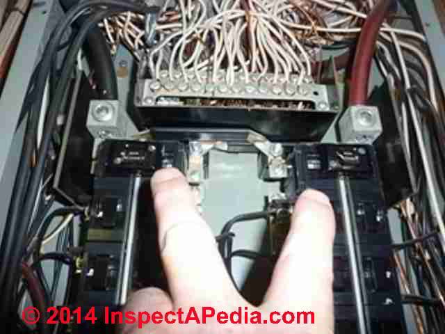
This video shows how to change a circuit breaker in a Pushmatic electrical panel aka Pushmatic load center. Twelve-gauge wire suits 15- to 20-amp breakers. A neutral wire is not used in this circuit.
I have a bulldog panel in my old home that was installed in an electrical system upgrade in the early 1960s. A wiring diagram is a streamlined standard pictorial depiction of an electric circuit. This is a distinctive panel because it is the only electrical panel brand that does not have switches that flip left and right.
The installation is similar to a 3-wire system but includes the fourth neutral wire that connects to the neutral bus bar in the panel and the neutral terminal on the receptacle. There is a 60 amp breaker that is the second breaker that says main lights on the breaker and main 110v on the panel cover.
 Pushmatic Panel Change Youtube
Pushmatic Breaker Wiring Diagram Fl112 Wiring Diagram Fuses Boxs Tukune Jeanjaures37 Fr
 Main Electrical Panel Disconnect Switch Installation Defects Inspection
 How To Wire A Breaker Circuit With Pictures Wikihow
 Siemens 15 Amp Tandem Single Pole Type Qt Circuit Breaker Q1515u The Home Depot
0 Comments